BECA 010

Description
The BECA 010 profile is an O'Ring, a circular ring with a round cross-section, made from rubber.
Advantages
Compact design
Easy assembly
Economic solution
Symmetry that reduces the risks of an assembly error
Technical data
| Temperature | -60°C / +200°C |
|---|---|
| Pressure | * |
| Speed | * |
| Medias | The majority of liquid, gaseous or chemical product fluids depending on the type of material selected. Refer to our fluids-materials compatibility guide. |
Applications
All types of applications
Materials
ACM 70 Shore A
AEM 70 Shore A
EPDM 70 Shore A
FKM 70 Shore A
HNBR 70 Shore A
NBR 70 Shore A
VMQ 70 Shore A
Dimensions
| Part number | Inside diameter Ød1 |
Cross-section Ød2 |
N° d'identification selon normes | ||||||||
|---|---|---|---|---|---|---|---|---|---|---|---|
| AS 568A | AS 568A BS 1806 |
ISO 3601 G | DIN 3771 | NFT 47-501 G | Bague R | JIS B2401 | SMS 1586 | BS 4518 | |||
|
010.1BJ20
|
40,50 | 4,50 | - | - | - | - | - | - | - | - | - |
|
010.1A545
|
40,64 | 5,33 | 326 | x | x | - | - | R29 | - | - | - |
|
010.40735
|
40,70 | 3,50 | - | - | - | - | - | - | P41 | - | - |
|
010.1A382
|
40,87 | 3,53 | 223 | x | x | - | - | - | - | - | - |
|
010.1A217
|
40,94 | 2,62 | 130 | x | x | - | - | - | - | - | - |
|
010.1B242
|
41,00 | 1,50 | - | - | - | - | - | - | - | - | - |
|
010.1A068
|
41,00 | 1,78 | 030 | x | x | - | - | - | - | - | - |
|
010.1B597
|
41,00 | 2,00 | - | - | - | - | - | - | - | - | - |
|
010.1B933
|
41,00 | 2,50 | - | - | - | - | - | - | - | - | - |
|
010.1BF00
|
41,00 | 3,00 | - | - | - | - | - | - | - | - | - |
|
010.1BM25
|
41,00 | 3,50 | - | - | - | - | - | - | - | - | - |
|
010.1BS42
|
41,00 | 4,00 | - | - | - | - | - | - | - | - | - |
|
010.1BZ77
|
41,00 | 4,50 | - | - | - | - | - | - | - | - | - |
|
010.1BY56
|
41,00 | 5,00 | - | - | - | - | - | - | - | - | - |
|
010.1B62F
|
41,00 | 6,00 | - | - | - | - | - | - | - | - | - |
|
010.41218
|
41,20 | 1,80 | - | - | - | - | B0412GN | - | - | - | - |
|
010.41226
|
41,20 | 2,65 | - | - | - | - | B0412GN | - | - | - | - |
|
010.1BP93
|
41,20 | 3,55 | - | - | - | x | B0412GN | - | - | - | - |
|
010.1B80B
|
41,20 | 5,30 | - | - | - | x | B0412GN | - | - | - | - |
|
010.1A383
|
41,28 | 3,53 | - | - | - | - | - | - | - | - | - |
|
010.1A526
|
41,40 | 5,30 | - | - | - | - | - | - | - | - | - |
|
010.1A312
|
41,50 | 3,00 | - | - | - | - | - | - | - | - | x |
|
010.1B64F
|
41,50 | 6,00 | - | - | - | - | - | - | - | - | - |
|
010.1A159
|
41,60 | 2,40 | - | - | - | - | - | - | - | - | x |
|
010.41735
|
41,70 | 3,50 | - | - | - | - | - | - | P42 | - | - |
|
010.1B286
|
42,00 | 1,50 | - | - | - | - | - | - | - | - | - |
|
010.1B600
|
42,00 | 2,00 | - | - | - | - | - | - | - | - | - |
|
010.1B936
|
42,00 | 2,50 | - | - | - | - | - | - | - | - | - |
|
010.1BF03
|
42,00 | 3,00 | - | - | - | - | - | - | - | - | - |
|
010.1BM24
|
42,00 | 3,50 | - | - | - | - | - | - | - | - | - |
|
010.1BS45
|
42,00 | 4,00 | - | - | - | - | - | - | - | - | - |
|
010.1BZ80
|
42,00 | 4,50 | - | - | - | - | - | - | - | - | - |
|
010.1BY57
|
42,00 | 5,00 | - | - | - | - | - | - | - | - | - |
|
010.1B60F
|
42,00 | 6,00 | - | - | - | - | - | - | - | - | - |
|
010.1A313
|
42,20 | 3,00 | - | - | - | - | - | - | - | - | - |
|
010.42303
|
42,30 | 3,00 | - | - | - | - | - | - | - | x | - |
|
010.42518
|
42,50 | 1,80 | - | - | - | - | B0425GN | - | - | - | - |
|
010.42526
|
42,50 | 2,65 | - | - | - | - | B0425GN | - | - | - | - |
|
010.1A314
|
42,50 | 3,00 | - | - | - | - | - | - | - | - | x |
|
010.1BI92
|
42,50 | 3,55 | - | - | - | x | B0425GN | - | - | - | - |
|
010.1B81B
|
42,50 | 5,30 | - | - | - | x | B0425GN | - | - | - | - |
|
010.1A218
|
42,52 | 2,62 | 131 | x | x | - | - | - | - | - | - |
|
010.1A384
|
42,86 | 3,53 | - | - | - | - | - | - | - | - | - |
|
010.1B241
|
43,00 | 1,50 | - | - | - | - | - | - | - | - | - |
|
010.1B603
|
43,00 | 2,00 | - | - | - | - | - | - | - | - | - |
|
010.1B939
|
43,00 | 2,50 | - | - | - | - | - | - | - | - | - |
|
010.1BF06
|
43,00 | 3,00 | - | - | - | - | - | - | - | - | - |
|
010.1BM27
|
43,00 | 3,50 | - | - | - | - | - | - | - | - | - |
|
010.1BS48
|
43,00 | 4,00 | - | - | - | - | - | - | - | - | - |
|
010.1BZ81
|
43,00 | 4,50 | - | - | - | - | - | - | - | - | - |
|
010.1BY60
|
43,00 | 5,00 | - | - | - | - | - | - | - | - | - |
|
010.1B63F
|
43,00 | 6,00 | - | - | - | - | - | - | - | - | - |
|
010.1A479
|
43,40 | 3,60 | - | - | - | - | - | - | - | - | - |
|
010.1A315
|
43,69 | 3,00 | 924 | - | - | - | - | - | - | - | - |
|
010.43718
|
43,70 | 1,80 | - | - | - | - | B0437GN | - | - | - | - |
|
010.43726
|
43,70 | 2,65 | - | - | - | - | B0437GN | - | - | - | - |
|
010.43735
|
43,70 | 3,50 | - | - | - | - | - | - | P44 | - | - |
|
010.1BP96
|
43,70 | 3,55 | - | - | - | x | B0437GN | - | - | - | - |
|
010.1B56A
|
43,70 | 5,30 | - | - | - | x | B0437GN | - | - | - | - |
|
010.1A546
|
43,82 | 5,33 | 327 | x | x | - | - | R30 | - | - | - |
|
010.1B307
|
44,00 | 1,50 | - | - | - | - | - | - | - | - | - |
|
010.1B605
|
44,00 | 2,00 | - | - | - | - | - | - | - | - | - |
|
010.1B942
|
44,00 | 2,50 | - | - | - | - | - | - | - | - | - |
|
010.1BF09
|
44,00 | 3,00 | - | - | - | - | - | - | - | - | - |
|
010.1BM30
|
44,00 | 3,50 | - | - | - | - | - | - | - | - | - |
|
010.1BS51
|
44,00 | 4,00 | - | - | - | - | - | - | - | - | - |
|
010.1BZ83
|
44,00 | 4,50 | - | - | - | - | - | - | - | - | - |
|
010.1BY63
|
44,00 | 5,00 | - | - | - | - | - | - | - | - | - |
|
010.1B65F
|
44,00 | 6,00 | - | - | - | - | - | - | - | - | - |
|
010.1A385
|
44,04 | 3,53 | 224 | x | x | - | - | - | - | - | - |
|
010.1A219
|
44,12 | 2,62 | 132 | x | x | - | - | - | - | - | - |
|
010.1A069
|
44,17 | 1,78 | 031 | x | x | - | - | - | - | - | - |
|
010.1A316
|
44,20 | 3,00 | - | - | - | - | - | - | - | x | - |
|
010.1A631
|
44,20 | 5,70 | - | - | - | - | - | - | - | x | - |
|
010.1A632
|
44,30 | 5,70 | - | - | - | - | - | - | - | - | x |
|
010.44431
|
44,40 | 3,10 | - | - | - | - | - | - | G45 | - | - |
|
010.1A317
|
44,50 | 3,00 | - | - | - | - | - | - | - | - | x |
|
010.1B67F
|
44,50 | 6,00 | - | - | - | - | - | - | - | - | - |
|
010.1A160
|
44,60 | 2,40 | - | - | - | - | - | - | - | - | x |
|
010.44735
|
44,70 | 3,50 | - | - | - | - | - | - | P45 | - | - |
|
010.1A386
|
44,95 | 3,53 | - | - | - | - | - | - | - | - | - |
|
010.1B287
|
45,00 | 1,50 | - | - | - | - | - | - | - | - | - |
|
010.04518
|
45,00 | 1,80 | - | - | - | - | B0450GN | - | - | - | - |
|
010.1B609
|
45,00 | 2,00 | - | - | - | - | - | - | - | - | - |
|
010.1B945
|
45,00 | 2,50 | - | - | - | - | - | - | - | - | - |
|
010.45265
|
45,00 | 2,65 | - | - | - | - | B0450GN | - | - | - | - |
|
010.1BF12
|
45,00 | 3,00 | - | - | - | - | - | - | - | - | - |
|
010.1BM33
|
45,00 | 3,50 | - | - | - | - | - | - | - | - | - |
|
010.1BP99
|
45,00 | 3,55 | - | - | - | x | B0450GN | - | - | - | - |
|
010.1BS54
|
45,00 | 4,00 | - | - | - | - | - | - | - | - | - |
|
010.1BZ86
|
45,00 | 4,50 | - | - | - | - | - | - | - | - | - |
|
010.1BY66
|
45,00 | 5,00 | - | - | - | - | - | - | - | - | - |
|
010.1B83B
|
45,00 | 5,30 | - | - | - | x | B0450GN | - | - | - | - |
|
010.1B66F
|
45,00 | 6,00 | - | - | - | - | - | - | - | - | - |
|
010.1A633
|
45,30 | 5,70 | - | - | - | - | - | - | - | - | x |
|
010.45624
|
45,60 | 2,40 | - | - | - | - | - | - | - | - | x |
|
010.1A220
|
45,69 | 2,62 | 133 | x | x | - | - | - | - | - | - |
|
010.45735
|
45,70 | 3,50 | - | - | - | - | - | - | P46 | - | - |
|
010.1B239
|
46,00 | 1,50 | - | - | - | - | - | - | - | - | - |
|
010.1B612
|
46,00 | 2,00 | - | - | - | - | - | - | - | - | - |
Materials
NBR (Nitrile Butadiene Rubber)
Nitrile rubber (NBR) is the general term for acrylonitrile-butadiene copolymer. The ACN content can vary between 18% and 50%. While the acrylonitrile content is important, the resistance to oil and fuel is more so. Conversely, the elasticity and compression set are not as good. The NBR has good mechanical properties and good wear resistance. However, its resistance to atmospheric agents and the ozone is relatively low.
| Chemical resistance | Aliphatic hydrocarbons (propane, butane, petroleum, diesel fuel) Mineral oils and greases Fire-resistant fluids (HFA, HFB and HFC) Diluted acids, alkaline and saline solutions for low temperatures Water (up to +100°C max) |
|---|---|
| Compatibility issue | Fuels with a high aromatic content Aromatic hydrocarbons (benzene) Chlorinated hydrocarbons (trichlorethylene) Polar solvents (ketone, acetone, acetic acid, ethylene-ester) Strong acids Glycol-based brake fluids Atmospheric and ozone agents |
| Temperature range | -30°C / +100°C (short-term peak at +120°C) -40°C / +100°C with special NBRs |
FKM (fluorinated rubber)
Depending on their structure and fluorine content, fluoroelastomers can vary in terms of chemical resistance and resistance to cold. This FKM-based rubber is very often used for high-temperature hydraulic and pneumatic systems, industrial valves, injection/fuel systems, motor seals and high-vacuum systems.
| Chemical resistance | Mineral oils and greases, ASTM n°1, IRM 902 and IRM 903 oils. Fire-resistant liquids (HFD) Silicone oils and greases Mineral and vegetable oils and greases Aliphatic hydrocarbons (propane, butane, petroleum) Aromatic hydrocarbons (benzene, toluene) Chlorinated hydrocarbons (trichlorethylene) Petrol (including high alcohol content) Atmospheric and ozone agents |
|---|---|
| Compatibility issue | Glycol-based brake fluids Ammoniac gas Organic acids with a low molecular weight (formic and acetic acids) |
| Temperature range | -20°C / +200°C (short-term peak at +230°C) -40°C / +200°C with special FKMs |
EPDM (Ethylene Propylene Diene Monomer rubber)
As an Ethylene Propylene Diene Monomer copolymer, EPDM is commonly used for hot water taps, cooling systems, brake systems, dishwashers and washing machines.
| Chemical resistance | Hot water and steam up to +150°C Glycol-based brake fluids (Dot 3 & 4) and silicone-based brake fluids (Dot 5) Organic and inorganic acids Cleaning agents, sodium and potassium alkalis Hydraulic fluids (HFD-R) Silicone oils and greases Polar solvents (alcohols, ketones and esters) Atmospheric and ozone agents |
|---|---|
| Compatibility issue | Mineral oils and greases Hydrocarbons Low impermeability to gas |
| Temperature range | -45°C / +150°C (short-term peak at +175°C) |
HNBR (Hydrogenated Nitrile Butadiene Rubber)
This HNBR-based elastomer is obtained through selective hydrogenation of the NBR's butadiene groups. It is commonly used for power-assisted steering and for air conditioning.
| Chemical resistance | Aliphatic hydrocarbons Mineral and vegetable oils and greases Fire-resistant fluids (HFA, HFB and HFC) Diluted acids, saline solutions and bases for low temperatures Water and steam up to +150°C Atmospheric and ozone agents |
|---|---|
| Compatibility issue | Chlorinated hydrocarbons Polar solvents (ketones, esters and ethers) Strong acids |
| Temperature range | -30°C / +150°C (short-term peak at +160°C) -40°C / +150°C with special HNBRs |
VMQ (silicone rubber: methyl vinyl polysiloxane)
This FVMQ-based rubber is very often used for fuel systems.
| Chemical resistance | Animal and vegetable oils and greases Moderate water temperature Diluted saline solutions Atmospheric and ozone agents |
|---|---|
| Compatibility issue | Superheated steam up to +120°C Chlorinated hydrocarbons with a low molecular weight (trichlorethylene) Aromatic hydrocarbons (benzene, toluene) |
| Temperature range | -60°C / +200°C (short-term peak at +230°C) |
FVMQ (fluorosilicone rubber)
The FVMQ has mechanical and physical properties that are very similar to those of VMQ. However, the FVMQ offers better resistance to fuels and mineral oils. However, resistance to hot air is not as good as that of VMQ.
| Chemical resistance | Aromatic mineral oils (IRM 903 oil) Fuels Aromatic hydrocarbons with a low molecular weight (benzene, toluene) |
|---|---|
| Temperature range | -70°C / +175°C |
ACM (Polyacrylate)
Polymers containing ethyl acrylate (or butyl acrylate) have a small amount of monomer, which is necessary for cross-linking; ACM is a material with better heat resistance than NBR. It is often used for automatic gearboxes.
| Chemical resistance | Mineral oils (motor oils, gear box oils, ATF oils) Atmospheric and ozone agents |
|---|---|
| Compatibility issue | Glycol-based brake fluids (Dot 3 & 4) Aromatic and chlorinated hydrocarbons Water and steam Acids, alkalis and amines |
| Temperature range | -25°C to + 150°C (short-term peak at +160°C) -35°C / +150°C with special ACMs |
AEM (ethylene acrylate rubber)
As a methyl acrylate and ethylene copolymer, AEM is considered to be better resistant to heat than ACM. Its characteristics make it an intermediary between ACM and FKM.
| Chemical resistance | Coolants Aggressive mineral oils Atmospheric agents Water |
|---|---|
| Compatibility issue | Aromatic solvents Strong acids Brake fluids Gearbox oils ATF oils |
| Temperature range | - 40°C à + 150°C |
CR (Polychloroprene)
This CR-based elastomer is used in the refrigeration industry and for ventilation systems. This chloroprene was the first synthetic rubber to be developed and marketed.
| Chemical resistance | Paraffinic mineral oils Silicone oils and greases Water and water-based solvents for use at low temperatures Refrigerant fluids Ammoniac Carbon dioxide Atmospheric and ozone agents |
|---|---|
| Limited chemical resistance | Naphthenic mineral oils Aliphatic hydrocarbons (propane, butane, petroleum) Glycol-based brake fluids |
| Compatibility issue | Aromatic hydrocarbons (benzene) Chlorinated hydrocarbons (trichlorethylene) Polar solvents (ketone, acetone, acetic acid and ethylene-ester) |
| Temperature range | -40°C / +100°C (short-term peak at +120°C) |
FFKM (perfluorinated rubber)
FFKM has the best resistance to high temperatures and an excellent chemical inertia. This FKM-based rubber is very often used for high-temperature hydraulic and pneumatic systems, industrial valves, injection/fuel systems, motor seals and high-vacuum systems.
| Chemical resistance | Aliphatic and aromatic hydrocarbons Polar solvents (ketones, esters, ethers) Organic and inorganic acids Water and steam High-vacuum systems |
|---|---|
| Problème de compatibilité | Coolants (R11, R12, R13, R113, R114, etc.) PFPE |
| Temperature range | -15°C / +320°C |
The table below gives an overview of the physical, chemical and mechanical characteristics for each of the materials.
| Characteristics/Materials | ACM | AEM | CR | EPDM | FFKM | FKM | FVMQ | HNBR | NBR | VMQ |
|---|---|---|---|---|---|---|---|---|---|---|
| Resistance to abrasion | 2 | 3 | 2 | 2 | 4 | 2 | 4 | 2 | 2 | 4 |
| Acid resistant | 4 | 3 | 2 | 2 | 1 | 1 | 3 | 1 | 3 | 3 |
| Resistance to chemicals | 4 | 2 | 2 | 1 | 1 | 1 | 1 | 2 | 2 | 2 |
| Resistance to cold | 4 | 2 | 2 | 2 | 3 | 4 | 2 | 2 | 2 | 2 |
| Dynamic properties | 3 | 3 | 3 | 2 | 3 | 2 | 4 | 1 | 2 | 4 |
| Electrical properties | 3 | 3 | 3 | 2 | 1 | 4 | 1 | 3 | 3 | 1 |
| Resistance to fire | 4 | 4 | 2 | 4 | 1 | 1 | 2 | 4 | 4 | 3 |
| Resistance to heat | 1 | 1 | 2 | 2 | 1 | 1 | 1 | 1 | 2 | 1 |
| Sealing water | 1 | 1 | 2 | 2 | 2 | 2 | 4 | 2 | 2 | 4 |
| Resistance to oil | 1 | 3 | 2 | 4 | 1 | 1 | 2 | 1 | 1 | 2 |
| Resistance to ozone | 1 | 1 | 2 | 1 | 1 | 1 | 1 | 2 | 4 | 1 |
| Resistance to tearing | 2 | 3 | 3 | 1 | 4 | 3 | 4 | 2 | 2 | 4 |
| Tensile strength | 3 | 2 | 2 | 1 | 2 | 1 | 3 | 1 | 2 | 4 |
| Resistance to water / steam | 4 | 4 | 3 | 1 | 2 | 3 | 3 | 1 | 2 | 3 |
| Resistance to atmospheric agents | 1 | 1 | 1 | 1 | 1 | 1 | 1 | 2 | 3 | 1 |
1. excellent properties 2. Good properties 3. Average properties 4. Poor properties
Chemical compatibility
A "Chemical compatibility guide" catalogue can be downloaded from the Literature section. You can also use our online "Chemical compatibility" tool free of charge.
These two tools enable you to measure the behaviour of our materials that come into contact with the majority of existing fluids. The data displayed is the result of rigorous testing at the ambient temperature and takes previous publications into consideration. Test results are not fully representative because of the specific features of your application. The tests performed actually do not consider additives and impurities that may exist under actual conditions of use, nor the potential elevation of temperatures. Other parameters can also alter the behaviour of our materials, such as the hardness, persistence, abrasion, etc. We therefore recommend performing your own tests to verify the compatibility of our materials depending on your specific application. Our technical team can provide you with any additional information.
Design recommendations
The tolerances on the inside diameters Ød1 set out in the table below relate to standard ISO 3601-1:2008. If the dimensions of an O'Ring are not specified in standard ISO 3601-1:2008, we recommend that you calculate the tolerances to apply to the inside diameter Ød1 as follows:
Tolerance on Ød1 = ± [(d10′95 x 0,009) + 0,11]
| Inside diameter Ød1 |
Tol. | Inside diameter Ød1 |
Tol. | |
|---|---|---|---|---|
| 0,74 ≤ Ød1 ≤ 1,78 | ± 0,12 | 242,00 < Ød1 ≤ 244,00 | ± 1,77 | |
| 1,78 < Ød1 ≤ 3,00 | ± 0,13 | 244,00 < Ød1 ≤ 246,00 | ± 1,78 | |
| 3,00 < Ød1 ≤ 4,20 | ± 0,14 | 246,00 < Ød1 ≤ 247,00 | ± 1,79 | |
| 4,20 < Ød1 ≤ 5,50 | ± 0,15 | 247,00 < Ød1 ≤ 249,00 | ± 1,80 | |
| 5,50 < Ød1 ≤ 6,75 | ± 0,16 | 249,00 < Ød1 ≤ 250,00 | ± 1,81 | |
| 6,75 < Ød1 ≤ 8,10 | ± 0,17 | 250,00 < Ød1 ≤ 252,00 | ± 1,82 | |
| 8,10 < Ød1 ≤ 9,50 | ± 0,18 | 252,00 < Ød1 ≤ 253,00 | ± 1,83 | |
| 9,50 < Ød1 ≤ 10,69 | ± 0,19 | 253,00 < Ød1 ≤ 254,50 | ± 1,84 | |
| 10,69 < Ød1 ≤ 12,00 | ± 0,20 | 254,50 < Ød1 ≤ 256,00 | ± 1,85 | |
| 12,00 < Ød1 ≤ 13,30 | ± 0,21 | 256,00 < Ød1 ≤ 258,00 | ± 1,86 | |
| 13,30 < Ød1 ≤ 14,80 | ± 0,22 | 258,00 < Ød1 ≤ 259,00 | ± 1,87 | |
| 14,80 < Ød1 ≤ 16,00 | ± 0,23 | 259,00 < Ød1 ≤ 261,00 | ± 1,88 | |
| 16,00 < Ød1 ≤ 17,30 | ± 0,24 | 261,00 < Ød1 ≤ 263,00 | ± 1,89 | |
| 17,30 < Ød1 ≤ 18,72 | ± 0,25 | 263,00 < Ød1 ≤ 264,00 | ± 1,90 | |
| 18,72 < Ød1 ≤ 20,22 | ± 0,26 | 264,00 < Ød1 ≤ 266,00 | ± 1,91 | |
| 20,22 < Ød1 ≤ 21,50 | ± 0,27 | 266,00 < Ød1 ≤ 267,00 | ± 1,92 | |
| 21,50 < Ød1 ≤ 23,00 | ± 0,28 | 267,00 < Ød1 ≤ 269,00 | ± 1,93 | |
| 23,00 < Ød1 ≤ 24,20 | ± 0,29 | 269,00 < Ød1 ≤ 270,00 | ± 1,94 | |
| 24,20 < Ød1 ≤ 25,50 | ± 0,30 | 270,00 < Ød1 ≤ 272,00 | ± 1,95 | |
| 25,50 < Ød1 ≤ 27,00 | ± 0,31 | 272,00 < Ød1 ≤ 273,00 | ± 1,96 | |
| 27,00 < Ød1 ≤ 28,24 | ± 0,32 | 273,00 < Ød1 ≤ 274,50 | ± 1,97 | |
| 28,24 < Ød1 ≤ 29,70 | ± 0,33 | 274,50 < Ød1 ≤ 276,00 | ± 1,98 | |
| 29,70 < Ød1 ≤ 31,12 | ± 0,34 | 276,00 < Ød1 ≤ 278,00 | ± 1,99 | |
| 31,12 < Ød1 ≤ 32,50 | ± 0,35 | 278,00 < Ød1 ≤ 279,30 | ± 2,00 | |
| 32,50 < Ød1 ≤ 34,00 | ± 0,36 | 279,30 < Ød1 ≤ 281,00 | ± 2,01 | |
| 34,00 < Ød1 ≤ 35,20 | ± 0,37 | 281,00 < Ød1 ≤ 283,00 | ± 2,02 | |
| 35,20 < Ød1 ≤ 37,00 | ± 0,38 | 283,00 < Ød1 ≤ 284,00 | ± 2,03 | |
| 37,00 < Ød1 ≤ 38,00 | ± 0,39 | 284,00 < Ød1 ≤ 286,00 | ± 2,04 | |
| 38,00 < Ød1 ≤ 39,40 | ± 0,40 | 286,00 < Ød1 ≤ 287,00 | ± 2,05 | |
| 39,40 < Ød1 ≤ 40,87 | ± 0,41 | 287,00 < Ød1 ≤ 289,00 | ± 2,06 | |
| 40,87 < Ød1 ≤ 42,30 | ± 0,42 | 289,00 < Ød1 ≤ 290,00 | ± 2,07 | |
| 42,30 < Ød1 ≤ 43,70 | ± 0,43 | 290,00 < Ød1 ≤ 291,47 | ± 2,08 | |
| 43,70 < Ød1 ≤ 45,30 | ± 0,44 | 291,47 < Ød1 ≤ 293,00 | ± 2,09 | |
| 45,30 < Ød1 ≤ 46,99 | ± 0,45 | 293,00 < Ød1 ≤ 295,00 | ± 2,10 | |
| 46,99 < Ød1 ≤ 48,00 | ± 0,46 | 295,00 < Ød1 ≤ 297,00 | ± 2,11 | |
| 48,00 < Ød1 ≤ 49,30 | ± 0,47 | 297,00 < Ød1 ≤ 297,80 | ± 2,12 | |
| 49,30 < Ød1 ≤ 50,80 | ± 0,48 | 297,80 < Ød1 ≤ 299,30 | ± 2,13 | |
| 50,80 < Ød1 ≤ 52,30 | ± 0,49 | 299,30 < Ød1 ≤ 301,00 | ± 2,14 | |
| 52,30 < Ød1 ≤ 53,57 | ± 0,50 | 301,00 < Ød1 ≤ 303,00 | ± 2,15 | |
| 53,57 < Ød1 ≤ 55,00 | ± 0,51 | 303,00 < Ød1 ≤ 304,00 | ± 2,16 | |
| 55,00 < Ød1 ≤ 56,52 | ± 0,52 | 304,00 < Ød1 ≤ 306,00 | ± 2,17 | |
| 56,52 < Ød1 ≤ 58,00 | ± 0,53 | 306,00 < Ød1 ≤ 307,00 | ± 2,18 | |
| 58,00 < Ød1 ≤ 59,30 | ± 0,54 | 307,00 < Ød1 ≤ 309,00 | ± 2,19 | |
| 59,30 < Ød1 ≤ 61,00 | ± 0,55 | 309,00 < Ød1 ≤ 310,50 | ± 2,20 | |
| 61,00 < Ød1 ≤ 62,30 | ± 0,56 | 310,50 < Ød1 ≤ 312,00 | ± 2,21 | |
| 62,30 < Ød1 ≤ 64,00 | ± 0,57 | 312,00 < Ød1 ≤ 314,00 | ± 2,22 | |
| 64,00 < Ød1 ≤ 65,10 | ± 0,58 | 314,00 < Ød1 ≤ 315,00 | ± 2,23 | |
| 65,10 < Ød1 ≤ 66,60 | ± 0,59 | 315,00 < Ød1 ≤ 316,87 | ± 2,24 | |
| 66,60 < Ød1 ≤ 67,95 | ± 0,60 | 316,87 < Ød1 ≤ 318,00 | ± 2,25 | |
| 67,95 < Ød1 ≤ 69,40 | ± 0,61 | 318,00 < Ød1 ≤ 319,50 | ± 2,26 | |
| 69,40 < Ød1 ≤ 71,00 | ± 0,62 | 319,50 < Ød1 ≤ 321,50 | ± 2,27 | |
| 71,00 < Ød1 ≤ 72,39 | ± 0,63 | 321,50 < Ød1 ≤ 323,00 | ± 2,28 | |
| 72,39 < Ød1 ≤ 74,00 | ± 0,64 | 323,00 < Ød1 ≤ 325,00 | ± 2,29 | |
| 74,00 < Ød1 ≤ 75,57 | ± 0,65 | 325,00 < Ød1 ≤ 326,00 | ± 2,30 | |
| 75,57 < Ød1 ≤ 77,00 | ± 0,66 | 326,00 < Ød1 ≤ 328,00 | ± 2,31 | |
| 77,00 < Ød1 ≤ 78,50 | ± 0,67 | 328,00 < Ød1 ≤ 329,00 | ± 2,32 | |
| 78,50 < Ød1 ≤ 79,60 | ± 0,68 | 329,00 < Ød1 ≤ 331,00 | ± 2,33 | |
| 79,60 < Ød1 ≤ 81,00 | ± 0,69 | 331,00 < Ød1 ≤ 332,00 | ± 2,34 | |
| 81,00 < Ød1 ≤ 82,50 | ± 0,70 | 332,00 < Ød1 ≤ 334,00 | ± 2,35 | |
| 82,50 < Ød1 ≤ 84,00 | ± 0,71 | 334,00 < Ød1 ≤ 335,90 | ± 2,36 | |
| 84,00 < Ød1 ≤ 86,00 | ± 0,72 | 335,90 < Ød1 ≤ 337,00 | ± 2,37 | |
| 86,00 < Ød1 ≤ 87,00 | ± 0,73 | 337,00 < Ød1 ≤ 339,00 | ± 2,38 | |
| 87,00 < Ød1 ≤ 88,49 | ± 0,74 | 339,00 < Ød1 ≤ 340,00 | ± 2,39 | |
| 88,49 < Ød1 ≤ 90,00 | ± 0,75 | 340,00 < Ød1 ≤ 342,00 | ± 2,40 | |
| 90,00 < Ød1 ≤ 91,44 | ± 0,76 | 342,00 < Ød1 ≤ 343,00 | ± 2,41 | |
| 91,44 < Ød1 ≤ 93,00 | ± 0,77 | 343,00 < Ød1 ≤ 345,00 | ± 2,42 | |
| 93,00 < Ød1 ≤ 94,30 | ± 0,78 | 345,00 < Ød1 ≤ 347,00 | ± 2,43 | |
| 94,30 < Ød1 ≤ 96,00 | ± 0,79 | 347,00 < Ød1 ≤ 348,00 | ± 2,44 | |
| 96,00 < Ød1 ≤ 97,50 | ± 0,80 | 348,00 < Ød1 ≤ 350,00 | ± 2,45 | |
| 97,50 < Ød1 ≤ 99,00 | ± 0,81 | 350,00 < Ød1 ≤ 351,00 | ± 2,46 | |
| 99,00 < Ød1 ≤ 100,50 | ± 0,82 | 351,00 < Ød1 ≤ 353,00 | ± 2,47 | |
| 100,50 < Ød1 ≤ 101,60 | ± 0,83 | 353,00 < Ød1 ≤ 354,00 | ± 2,48 | |
| 101,60 < Ød1 ≤ 103,00 | ± 0,84 | 354,00 < Ød1 ≤ 356,00 | ± 2,49 | |
| 103,00 < Ød1 ≤ 104,50 | ± 0,85 | 356,00 < Ød1 ≤ 358,00 | ± 2,50 | |
| 104,50 < Ød1 ≤ 106,00 | ± 0,86 | 358,00 < Ød1 ≤ 359,00 | ± 2,51 | |
| 106,00 < Ød1 ≤ 107,54 | ± 0,87 | 359,00 < Ød1 ≤ 361,00 | ± 2,52 | |
| 107,54 < Ød1 ≤ 109,00 | ± 0,88 | 361,00 < Ød1 ≤ 362,00 | ± 2,53 | |
| 109,00 < Ød1 ≤ 110,49 | ± 0,89 | 362,00 < Ød1 ≤ 364,00 | ± 2,54 | |
| 110,49 < Ød1 ≤ 112,00 | ± 0,90 | 364,00 < Ød1 ≤ 365,00 | ± 2,55 | |
| 112,00 < Ød1 ≤ 113,67 | ± 0,91 | 365,00 < Ød1 ≤ 367,00 | ± 2,56 | |
| 113,67 < Ød1 ≤ 115,00 | ± 0,92 | 367,00 < Ød1 ≤ 369,00 | ± 2,57 | |
| 115,00 < Ød1 ≤ 116,84 | ± 0,93 | 369,00 < Ød1 ≤ 370,00 | ± 2,58 | |
| 116,84 < Ød1 ≤ 118,00 | ± 0,94 | 370,00 < Ød1 ≤ 372,00 | ± 2,59 | |
| 118,00 < Ød1 ≤ 119,30 | ± 0,95 | 372,00 < Ød1 ≤ 373,00 | ± 2,60 | |
| 119,30 < Ød1 ≤ 121,00 | ± 0,96 | 373,00 < Ød1 ≤ 374,50 | ± 2,61 | |
| 121,00 < Ød1 ≤ 123,00 | ± 0,97 | 374,50 < Ød1 ≤ 376,00 | ± 2,62 | |
| 123,00 < Ød1 ≤ 123,83 | ± 0,98 | 376,00 < Ød1 ≤ 378,00 | ± 2,63 | |
| 123,83 < Ød1 ≤ 126,00 | ± 0,99 | 378,00 < Ød1 ≤ 379,30 | ± 2,64 | |
| 126,00 < Ød1 ≤ 126,72 | ± 1,00 | 379,30 < Ød1 ≤ 381,00 | ± 2,65 | |
| 126,72 < Ød1 ≤ 129,00 | ± 1,01 | 381,00 < Ød1 ≤ 383,00 | ± 2,66 | |
| 129,00 < Ød1 ≤ 129,77 | ± 1,02 | 383,00 < Ød1 ≤ 384,00 | ± 2,67 | |
| 129,77 < Ød1 ≤ 131,50 | ± 1,03 | 384,00 < Ød1 ≤ 386,00 | ± 2,68 | |
| 131,50 < Ød1 ≤ 132,72 | ± 1,04 | 386,00 < Ød1 ≤ 387,00 | ± 2,69 | |
| 132,72 < Ød1 ≤ 134,30 | ± 1,05 | 387,00 < Ød1 ≤ 389,00 | ± 2,70 | |
| 134,30 < Ød1 ≤ 135,76 | ± 1,06 | 389,00 < Ød1 ≤ 391,00 | ± 2,71 | |
| 135,76 < Ød1 ≤ 138,00 | ± 1,07 | 391,00 < Ød1 ≤ 392,00 | ± 2,72 | |
| 138,00 < Ød1 ≤ 138,94 | ± 1,08 | 392,00 < Ød1 ≤ 394,00 | ± 2,73 | |
| 138,94 < Ød1 ≤ 140,50 | ± 1,09 | 394,00 < Ød1 ≤ 395,00 | ± 2,74 | |
| 140,50 < Ød1 ≤ 142,00 | ± 1,10 | 395,00 < Ød1 ≤ 397,00 | ± 2,75 | |
| 142,00 < Ød1 ≤ 144,00 | ± 1,11 | 397,00 < Ød1 ≤ 398,00 | ± 2,76 | |
| 144,00 < Ød1 ≤ 145,00 | ± 1,12 | 398,00 < Ød1 ≤ 400,00 | ± 2,77 | |
| 145,00 < Ød1 ≤ 147,00 | ± 1,13 | 400,00 < Ød1 ≤ 402,00 | ± 2,78 | |
| 147,00 < Ød1 ≤ 148,00 | ± 1,14 | 402,00 < Ød1 ≤ 403,00 | ± 2,79 | |
| 148,00 < Ød1 ≤ 149,23 | ± 1,15 | 403,00 < Ød1 ≤ 405,00 | ± 2,80 | |
| 149,23 < Ød1 ≤ 151,00 | ± 1,16 | 405,00 < Ød1 ≤ 406,00 | ± 2,81 | |
| 151,00 < Ød1 ≤ 152,50 | ± 1,17 | 406,00 < Ød1 ≤ 408,00 | ± 2,82 | |
| 152,50 < Ød1 ≤ 154,00 | ± 1,18 | 408,00 < Ød1 ≤ 409,00 | ± 2,83 | |
| 154,00 < Ød1 ≤ 155,50 | ± 1,19 | 409,00 < Ød1 ≤ 411,00 | ± 2,84 | |
| 155,50 < Ød1 ≤ 157,00 | ± 1,20 | 411,00 < Ød1 ≤ 413,00 | ± 2,85 | |
| 157,00 < Ød1 ≤ 158,34 | ± 1,21 | 413,00 < Ød1 ≤ 414,00 | ± 2,86 | |
| 158,34 < Ød1 ≤ 160,00 | ± 1,22 | 414,00 < Ød1 ≤ 416,00 | ± 2,87 | |
| 160,00 < Ød1 ≤ 161,30 | ± 1,23 | 416,00 < Ød1 ≤ 417,00 | ± 2,88 | |
| 161,30 < Ød1 ≤ 163,00 | ± 1,24 | 417,00 < Ød1 ≤ 419,00 | ± 2,89 | |
| 163,00 < Ød1 ≤ 164,30 | ± 1,25 | 419,00 < Ød1 ≤ 421,00 | ± 2,90 | |
| 164,30 < Ød1 ≤ 166,00 | ± 1,26 | 421,00 < Ød1 ≤ 422,00 | ± 2,91 | |
| 166,00 < Ød1 ≤ 167,50 | ± 1,27 | 422,00 < Ød1 ≤ 424,00 | ± 2,92 | |
| 167,50 < Ød1 ≤ 169,00 | ± 1,28 | 424,00 < Ød1 ≤ 425,00 | ± 2,93 | |
| 169,00 < Ød1 ≤ 170,69 | ± 1,29 | 425,00 < Ød1 ≤ 427,00 | ± 2,94 | |
| 170,69 < Ød1 ≤ 172,00 | ± 1,30 | 427,00 < Ød1 ≤ 428,00 | ± 2,95 | |
| 172,00 < Ød1 ≤ 173,87 | ± 1,31 | 428,00 < Ød1 ≤ 430,00 | ± 2,96 | |
| 173,87 < Ød1 ≤ 175,00 | ± 1,32 | 430,00 < Ød1 ≤ 432,00 | ± 2,97 | |
| 175,00 < Ød1 ≤ 177,00 | ± 1,33 | 432,00 < Ød1 ≤ 433,00 | ± 2,98 | |
| 177,00 < Ød1 ≤ 178,00 | ± 1,34 | 433,00 < Ød1 ≤ 435,00 | ± 2,99 | |
| 178,00 < Ød1 ≤ 179,50 | ± 1,35 | 435,00 < Ød1 ≤ 436,00 | ± 3,00 | |
| 179,50 < Ød1 ≤ 181,00 | ± 1,36 | 436,00 < Ød1 ≤ 438,00 | ± 3,01 | |
| 181,00 < Ød1 ≤ 182,50 | ± 1,37 | 438,00 < Ød1 ≤ 439,30 | ± 3,02 | |
| 182,50 < Ød1 ≤ 184,00 | ± 1,38 | 439,30 < Ød1 ≤ 441,00 | ± 3,03 | |
| 184,00 < Ød1 ≤ 186,00 | ± 1,39 | 441,00 < Ød1 ≤ 443,00 | ± 3,04 | |
| 186,00 < Ød1 ≤ 187,00 | ± 1,40 | 443,00 < Ød1 ≤ 444,00 | ± 3,05 | |
| 187,00 < Ød1 ≤ 189,00 | ± 1,41 | 444,00 < Ød1 ≤ 446,00 | ± 3,06 | |
| 189,00 < Ød1 ≤ 190,00 | ± 1,42 | 446,00 < Ød1 ≤ 447,00 | ± 3,07 | |
| 190,00 < Ød1 ≤ 192,00 | ± 1,43 | 447,00 < Ød1 ≤ 449,00 | ± 3,08 | |
| 192,00 < Ød1 ≤ 193,00 | ± 1,44 | 449,00 < Ød1 ≤ 451,00 | ± 3,09 | |
| 193,00 < Ød1 ≤ 195,00 | ± 1,45 | 451,00 < Ød1 ≤ 452,00 | ± 3,10 | |
| 195,00 < Ød1 ≤ 196,22 | ± 1,46 | 452,00 < Ød1 ≤ 454,00 | ± 3,11 | |
| 196,22 < Ød1 ≤ 198,00 | ± 1,47 | 454,00 < Ød1 ≤ 455,00 | ± 3,12 | |
| 198,00 < Ød1 ≤ 199,10 | ± 1,48 | 455,00 < Ød1 ≤ 457,00 | ± 3,13 | |
| 199,10 < Ød1 ≤ 201,00 | ± 1,49 | 457,00 < Ød1 ≤ 459,00 | ± 3,14 | |
| 201,00 < Ød1 ≤ 202,57 | ± 1,50 | 459,00 < Ød1 ≤ 460,00 | ± 3,15 | |
| 202,57 < Ød1 ≤ 204,00 | ± 1,51 | 460,00 < Ød1 ≤ 462,00 | ± 3,16 | |
| 204,00 < Ød1 ≤ 206,00 | ± 1,52 | 462,00 < Ød1 ≤ 463,00 | ± 3,17 | |
| 206,00 < Ød1 ≤ 207,00 | ± 1,53 | 463,00 < Ød1 ≤ 465,00 | ± 3,18 | |
| 207,00 < Ød1 ≤ 208,50 | ± 1,54 | 465,00 < Ød1 ≤ 467,00 | ± 3,19 | |
| 208,50 < Ød1 ≤ 210,00 | ± 1,55 | 467,00 < Ød1 ≤ 468,00 | ± 3,20 | |
| 210,00 < Ød1 ≤ 212,00 | ± 1,56 | 468,00 < Ød1 ≤ 470,00 | ± 3,21 | |
| 212,00 < Ød1 ≤ 213,00 | ± 1,57 | 470,00 < Ød1 ≤ 471,00 | ± 3,22 | |
| 213,00 < Ød1 ≤ 214,50 | ± 1,58 | 471,00 < Ød1 ≤ 473,00 | ± 3,23 | |
| 214,50 < Ød1 ≤ 216,00 | ± 1,59 | 473,00 < Ød1 ≤ 475,00 | ± 3,24 | |
| 216,00 < Ød1 ≤ 218,00 | ± 1,60 | 475,00 < Ød1 ≤ 476,00 | ± 3,25 | |
| 218,00 < Ød1 ≤ 219,00 | ± 1,61 | 476,00 < Ød1 ≤ 478,00 | ± 3,26 | |
| 219,00 < Ød1 ≤ 221,00 | ± 1,62 | 478,00 < Ød1 ≤ 479,00 | ± 3,27 | |
| 221,00 < Ød1 ≤ 222,00 | ± 1,63 | 479,00 < Ød1 ≤ 481,00 | ± 3,28 | |
| 222,00 < Ød1 ≤ 224,00 | ± 1,64 | 481,00 < Ød1 ≤ 482,00 | ± 3,29 | |
| 224,00 < Ød1 ≤ 226,00 | ± 1,65 | 482,00 < Ød1 ≤ 484,00 | ± 3,30 | |
| 226,00 < Ød1 ≤ 227,00 | ± 1,66 | 484,00 < Ød1 ≤ 486,00 | ± 3,31 | |
| 227,00 < Ød1 ≤ 228,19 | ± 1,67 | 486,00 < Ød1 ≤ 487,00 | ± 3,32 | |
| 228,19 < Ød1 ≤ 230,00 | ± 1,68 | 487,00 < Ød1 ≤ 489,00 | ± 3,33 | |
| 230,00 < Ød1 ≤ 232,00 | ± 1,69 | 489,00 < Ød1 ≤ 490,00 | ± 3,34 | |
| 232,00 < Ød1 ≤ 233,00 | ± 1,70 | 490,00 < Ød1 ≤ 492,00 | ± 3,35 | |
| 233,00 < Ød1 ≤ 234,32 | ± 1,71 | 492,00 < Ød1 ≤ 494,00 | ± 3,36 | |
| 234,32 < Ød1 ≤ 236,00 | ± 1,72 | 494,00 < Ød1 ≤ 495,00 | ± 3,37 | |
| 236,00 < Ød1 ≤ 237,50 | ± 1,73 | 495,00 < Ød1 ≤ 497,00 | ± 3,38 | |
| 237,50 < Ød1 ≤ 239,00 | ± 1,74 | 497,00 < Ød1 ≤ 498,00 | ± 3,39 | |
| 239,00 < Ød1 ≤ 240,67 | ± 1,75 | 498,00 < Ød1 ≤ 500,00 | ± 3,40 | |
| 240,67 < Ød1 ≤ 242,00 | ± 1,76 | 500,00 < Ød1 ≤ 504,00 | ± 3,41 |
The tolerances on standardised cross-sections Ød2 set out in the table below relate to standard ISO 3601-1:2008.
| Cross-section Ød2 |
Tolerances |
|---|---|
| 1,02 | ± 0,08 |
| 1,27 | ± 0,08 |
| 1,52 | ± 0,08 |
| 1,78 | ± 0,08 |
| 2,62 | ± 0,09 |
| 3,53 | ± 0,10 |
| 5,33 | ± 0,13 |
| 6,99 | ± 0,15 |
The tolerances on non-standardised cross-sections Ød2 set out in the table below relate to standard ISO 3601-1:2008.
| Cross-section Ød2 |
Tolerances |
|---|---|
| 0,80 < d2 ≤ 2,25 | ± 0,08 |
| 2,25 < d2 ≤ 3,15 | ± 0,09 |
| 3,15 < d2 ≤ 4,50 | ± 0,10 |
| 4,50 < d2 ≤ 6,30 | ± 0,13 |
| 6,30 < d2 ≤ 8,40 | ± 0,15 |
| 8,40 < d2 ≤ 10,00 | ± 0,21 |
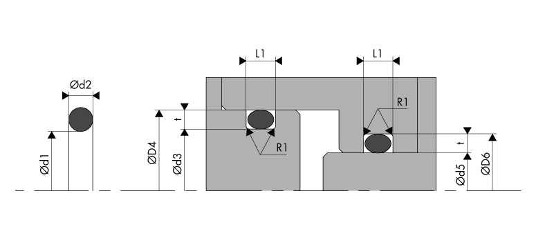
The O'Ring ensures sealing under radial deformation at the cross-section Ød2.
For rod sealing (inside sealing), the dimension of the O'Ring should be selected so that the outside diameter of the O'Ring is 0.5% to 5% greater than the groove diameter Ød6.
For piston sealing (outside sealing), the dimension of the O'Ring should be selected so that the inside diameter Ød1 of the O'Ring is 0.5% to 8% smaller than the groove diameter Ød3.
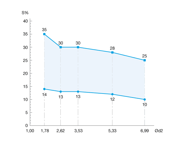
The table below sets out the tightening values (min and max) according to the cross-section Ød2
The table below sets out the design recommendations - Rectangular groove - Radial static pneumatic and hydraulic sealing
| Cross-section Ød2 |
Groove depth t 0/+0,05 |
Groove width L1 0/+0,20 |
Groove radius R1 |
|---|---|---|---|
| 0,50 | 0,35 | 1,00 | 0,20 |
| 0,74 | 0,50 | 1,40 | 0,20 |
| 1,00 | 0,72 | 1,60 | 0,20 |
| 1,02 | 0,72 | 1,65 | 0,20 |
| 1,20 | 0,85 | 1,90 | 0,20 |
| 1,25 | 0,90 | 1,90 | 0,20 |
| 1,27 | 0,90 | 2,00 | 0,20 |
| 1,30 | 0,95 | 2,00 | 0,20 |
| 1,42 | 1,05 | 2,20 | 0,30 |
| 1,50 | 1,10 | 2,20 | 0,30 |
| 1,52 | 1,10 | 2,30 | 0,30 |
| 1,53 | 1,10 | 2,30 | 0,30 |
| 1,60 | 1,15 | 2,50 | 0,30 |
| 1,63 | 1,20 | 2,40 | 0,30 |
| 1,78 | 1,30 | 2,70 | 0,30 |
| 1,80 | 1,30 | 2,70 | 0,30 |
| 1,83 | 1,35 | 2,70 | 0,30 |
| 1,90 | 1,40 | 2,80 | 0,30 |
| 1,98 | 1,50 | 2,80 | 0,30 |
| 2,00 | 1,50 | 2,90 | 0,30 |
| 2,08 | 1,55 | 3,00 | 0,30 |
| 2,10 | 1,55 | 3,00 | 0,30 |
| 2,20 | 1,60 | 3,20 | 0,30 |
| 2,21 | 1,60 | 3,20 | 0,30 |
| 2,30 | 1,75 | 3,20 | 0,30 |
| 2,34 | 1,75 | 3,30 | 0,30 |
| 2,40 | 1,80 | 3,40 | 0,30 |
| 2,46 | 1,85 | 3,50 | 0,30 |
| 2,50 | 1,90 | 3,50 | 0,30 |
| 2,62 | 2,00 | 3,60 | 0,30 |
| 2,65 | 2,00 | 3,70 | 0,30 |
| 2,70 | 2,05 | 3,80 | 0,30 |
| 2,80 | 2,10 | 4,30 | 0,60 |
| 2,92 | 2,20 | 4,50 | 0,60 |
| 2,95 | 2,20 | 4,50 | 0,60 |
| 3,00 | 2,30 | 4,50 | 0,60 |
| 3,10 | 2,40 | 4,60 | 0,60 |
| 3,15 | 2,45 | 4,60 | 0,60 |
| 3,50 | 2,70 | 5,10 | 0,60 |
| 3,53 | 2,70 | 5,10 | 0,60 |
| 3,55 | 2,70 | 5,20 | 0,60 |
| 3,60 | 2,80 | 5,20 | 0,60 |
| 4,00 | 3,10 | 5,60 | 0,60 |
| 4,50 | 3,55 | 6,20 | 0,60 |
| 5,00 | 4,00 | 6,70 | 0,60 |
| 5,30 | 4,30 | 6,90 | 0,60 |
| 5,33 | 4,30 | 7,10 | 0,60 |
| 5,50 | 4,50 | 7,10 | 0,60 |
| 5,70 | 4,60 | 7,40 | 0,60 |
| 6,00 | 4,90 | 7,80 | 0,60 |
| 6,50 | 5,40 | 8,70 | 1,00 |
| 6,99 | 5,80 | 9,30 | 1,00 |
| 7,00 | 5,80 | 9,50 | 1,00 |
| 7,50 | 6,30 | 9,70 | 1,00 |
| 8,00 | 6,70 | 10,20 | 1,00 |
| 8,40 | 7,10 | 10,50 | 1,00 |
| 9,00 | 7,65 | 12,30 | 1,50 |
| 9,50 | 8,20 | 12,70 | 1,50 |
| 10,00 | 8,60 | 15,10 | 2,00 |
| 12,00 | 10,30 | 17,00 | 2,00 |
These values are provided for information purposes only. We recommend refining your design using our O'Ring calculator, which is available free in the "Tools" tab on the website.
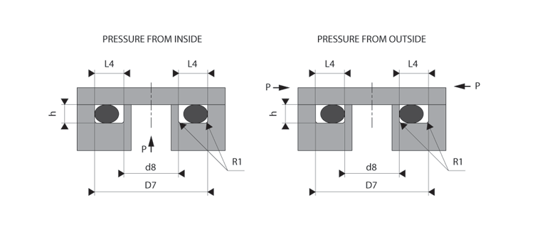
Flange and cover sealing is generally ensured by an O'Ring that is subject to axial deformation. The groove dimensions are determined according to the direction of the pressure.
When the pressure is directed from the outside in, the inside diameter Ød1 of the O'Ring must be 0% to 2% less than the inside diameter of the groove.
On the other hand, when the pressure is directed from the inside out, the outside diameter of the O'Ring must be 0% to 2% greater than the outside diameter of the groove.
These recommendations depend on the dimensions of the O-ring concerned.
The table below sets out the tightening values (min and max) according to the cross-section Ød2
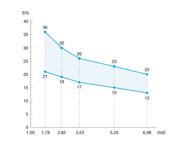
The table below sets out the design recommendations - Rectangular groove - Axial static sealing
| Cross-section Ød2 |
Groove depth h 0/+0,05 |
Groove width L4 0/+0,20 |
Radius R1 |
|---|---|---|---|
| 0,50 | 0,33 | 1,10 | 0,20 |
| 0,74 | 0,45 | 1,60 | 0,20 |
| 1,00 | 0,65 | 1,90 | 0,20 |
| 1,02 | 0,67 | 1,90 | 0,20 |
| 1,20 | 0,81 | 2,10 | 0,20 |
| 1,25 | 0,85 | 2,10 | 0,20 |
| 1,27 | 0,89 | 2,10 | 0,20 |
| 1,30 | 0,91 | 2,10 | 0,20 |
| 1,42 | 1,00 | 2,30 | 0,30 |
| 1,50 | 1,05 | 2,40 | 0,30 |
| 1,52 | 1,07 | 2,40 | 0,30 |
| 1,53 | 1,08 | 2,40 | 0,30 |
| 1,60 | 1,15 | 2,50 | 0,30 |
| 1,63 | 1,15 | 2,50 | 0,30 |
| 1,78 | 1,30 | 2,70 | 0,30 |
| 1,80 | 1,30 | 2,80 | 0,30 |
| 1,83 | 1,35 | 2,80 | 0,30 |
| 1,90 | 1,40 | 2,90 | 0,30 |
| 1,98 | 1,45 | 3,00 | 0,30 |
| 2,00 | 1,45 | 3,00 | 0,30 |
| 2,08 | 1,50 | 3,10 | 0,30 |
| 2,10 | 1,50 | 3,20 | 0,30 |
| 2,20 | 1,60 | 3,30 | 0,30 |
| 2,21 | 1,60 | 3,30 | 0,30 |
| 2,30 | 1,65 | 3,40 | 0,30 |
| 2,34 | 1,70 | 3,40 | 0,30 |
| 2,40 | 1,75 | 3,50 | 0,30 |
| 2,46 | 1,80 | 3,60 | 0,30 |
| 2,50 | 1,80 | 3,70 | 0,30 |
| 2,62 | 1,95 | 3,70 | 0,30 |
| 2,65 | 2,00 | 3,70 | 0,30 |
| 2,70 | 2,05 | 3,80 | 0,30 |
| 2,80 | 2,15 | 4,00 | 0,60 |
| 2,92 | 2,20 | 4,20 | 0,60 |
| 2,95 | 2,25 | 4,20 | 0,60 |
| 3,00 | 2,30 | 4,30 | 0,60 |
| 3,10 | 2,40 | 4,40 | 0,60 |
| 3,15 | 2,40 | 4,50 | 0,60 |
| 3,50 | 2,70 | 4,80 | 0,60 |
| 3,53 | 2,75 | 4,80 | 0,60 |
| 3,55 | 2,80 | 4,80 | 0,60 |
| 3,60 | 2,85 | 4,90 | 0,60 |
| 4,00 | 3,20 | 5,30 | 0,60 |
| 4,50 | 3,60 | 5,80 | 0,60 |
| 5,00 | 4,00 | 6,50 | 0,60 |
| 5,30 | 4,20 | 6,90 | 0,60 |
| 5,33 | 4,30 | 6,80 | 0,60 |
| 5,50 | 4,50 | 6,90 | 0,60 |
| 5,70 | 4,70 | 7,10 | 0,60 |
| 6,00 | 4,90 | 7,40 | 0,60 |
| 6,50 | 5,30 | 8,40 | 1,00 |
| 6,99 | 5,80 | 8,80 | 1,00 |
| 7,00 | 5,80 | 8,80 | 1,00 |
| 7,50 | 6,30 | 9,20 | 1,00 |
| 8,00 | 6,70 | 9,80 | 1,00 |
| 8,40 | 7,20 | 10,00 | 1,00 |
| 9,00 | 7,60 | 11,50 | 1,50 |
| 9,50 | 8,00 | 12,10 | 1,50 |
| 10,00 | 8,70 | 13,10 | 2,00 |
| 12,00 | 10,40 | 15,30 | 2,00 |
These values are provided for information purposes only. We recommend refining your design using our O'Ring calculator, which is available free in the "Tools" tab on the website.
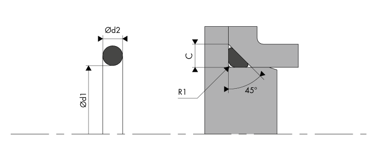
We use these types of fittings for cover or flange seals. This type of groove is difficult to machine and only allows a reduced swelling of the O'Ring. The values included in the table below set out all of our recommendations so that the connection between the cross-section Ød2 of the O'Ring and the length of the edge C gives a full seal. It is, however, preferable to use a rectangular groove as far as possible.
The table below sets out the design recommendations - Triangular groove - Static sealing.
| Cross-section Ød2 |
Length of the edge C |
Radius R1 |
|---|---|---|
| 1,78 - 1,80 | 2,40 | 0,30 |
| 1,83 | 2,50 | 0,30 |
| 1,90 | 2,55 | 0,30 |
| 1,98 | 2,70 | 0,30 |
| 2,00 | 2,70 | 0,40 |
| 2,08 | 2,70 | 0,40 |
| 2,10 | 2,70 | 0,40 |
| 2,20 | 3,00 | 0,40 |
| 2,21 | 3,00 | 0,40 |
| 2,30 | 3,10 | 0,40 |
| 2,34 | 3,15 | 0,40 |
| 2,40 | 3,20 | 0,40 |
| 2,46 | 3,30 | 0,40 |
| 2,50 | 3,40 | 0,60 |
| 2,62 - 2,65 | 3,50 | 0,60 |
| 2,70 | 3,60 | 0,60 |
| 2,80 | 3,80 | 0,60 |
| 2,92 | 3,90 | 0,60 |
| 2,95 | 4,00 | 0,60 |
| 3,00 | 4,00 | 0,60 |
| 3,10 | 4,20 | 0,60 |
| 3,15 | 4,30 | 0,60 |
| 3,50 | 4,80 | 0,60 |
| 3,53 - 3,55 | 4,80 | 0,90 |
| 3,60 | 4,90 | 0,90 |
| 4,00 | 5,40 | 1,20 |
| 4,50 | 6,10 | 1,20 |
| 5,00 | 6,80 | 1,20 |
| 5,30 - 5,33 | 7,20 | 1,50 |
| 5,50 | 7,50 | 1,50 |
| 5,70 | 7,70 | 1,50 |
| 6,00 | 8,10 | 1,50 |
| 6,50 | 8,80 | 1,50 |
| 6,99 - 7,00 | 9,50 | 2,00 |
| 7,50 | 10,10 | 2,00 |
| 8,00 | 10,80 | 2,00 |
| 8,40 | 11,40 | 2,00 |
| 9,00 | 13,20 | 2,00 |
| 9,50 | 13,90 | 2,00 |
| 10,00 | 14,70 | 2,50 |
| 12,00 | 17,60 | 2,50 |
These values are provided for information purposes only. We recommend refining your design using our O'Ring calculator, which is available free in the "Tools" tab on the website.
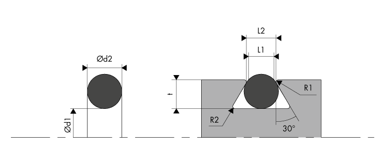
In specific cases, the O'Ring must be mechanically held in its groove. In this case, it is possible to mount the O'Ring in a trapezoidal groove. This installation is typically used in several static applications, and only from a cross-section of 3.53 mm. The installation dimensions are listed in the table below.
The table below sets out the design recommendations - Trapezoidal groove - Static pneumatic and hydraulic sealing
| Cross-section Ød2 |
Groove depth t +/-0,05 |
Groove width L1 +/-0,05 |
Groove width L2 +/-0,05 |
Groove radius R1 |
Groove radius R2 |
|---|---|---|---|---|---|
| 3,53 - 3,55 | 2,90 | 2,90 | 3,20 | 0,25 | 0,80 |
| 3,60 | 3,00 | 3,00 | 3,45 | 0,25 | 0,80 |
| 4,00 | 3,20 | 3,40 | 3,70 | 0,25 | 0,80 |
| 4,50 | 3,70 | 3,85 | 4,15 | 0,25 | 0,80 |
| 5,00 | 4,20 | 4,30 | 4,60 | 0,25 | 0,80 |
| 5,30 - 5,33 | 4,60 | 4,60 | 4,90 | 0,40 | 0,80 |
| 5,50 | 4,70 | 4,70 | 5,00 | 0,40 | 0,80 |
| 5,70 | 4,80 | 4,75 | 5,25 | 0,40 | 0,80 |
| 6,00 | 5,10 | 5,05 | 5,55 | 0,40 | 0,80 |
| 6,50 | 5,50 | 5,55 | 6,00 | 0,40 | 0,80 |
| 6,99 - 7,00 | 6,00 | 6,00 | 6,50 | 0,40 | 1,60 |
| 7,50 | 6,40 | 6,45 | 6.95 | 0,40 | 1,60 |
| 8,00 | 6,90 | 6,85 | 7,45 | 0,40 | 1,60 |
| 8,40 | 7,30 | 7,25 | 7,85 | 0,40 | 1,60 |
| 9,00 | 7,50 | 7,50 | 8,10 | 0,50 | 1,60 |
| 9,50 | 7,90 | 7,90 | 8,60 | 0,50 | 1,60 |
| 10,00 | 8,25 | 8,30 | 9,00 | 0,60 | 1,70 |
| 12,00 | 10,20 | 10,25 | 11,00 | 0,60 | 1,70 |
These values are provided for information purposes only. We recommend refining your design using our O'Ring calculator, which is available free in the "Tools" tab on the website.
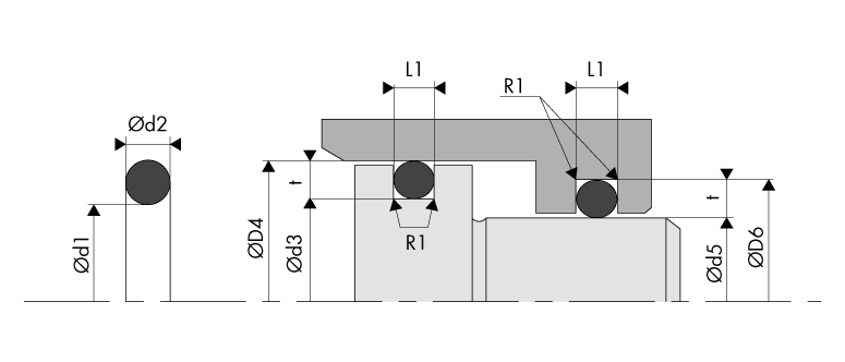
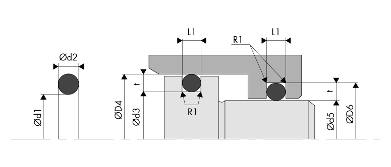
O'Rings can be used as sealing components for hydraulic applications in linear motion. However, they have an average efficiency and are only suitable for relatively low travel and frequencies. Other seal profiles are prioritised for such applications (see the hydraulic seals range).
For rod sealing (inside sealing), the dimension of the O'Ring should be selected so that the outside diameter of the O'Ring is 0.5% to 5% greater than the groove diameter Ød6.
For piston sealing (outside sealing), the dimension of the O'Ring should be selected so that the inside diameter Ød1 of the O'Ring is 0.5% to 5% smaller than the groove diameter Ød3.
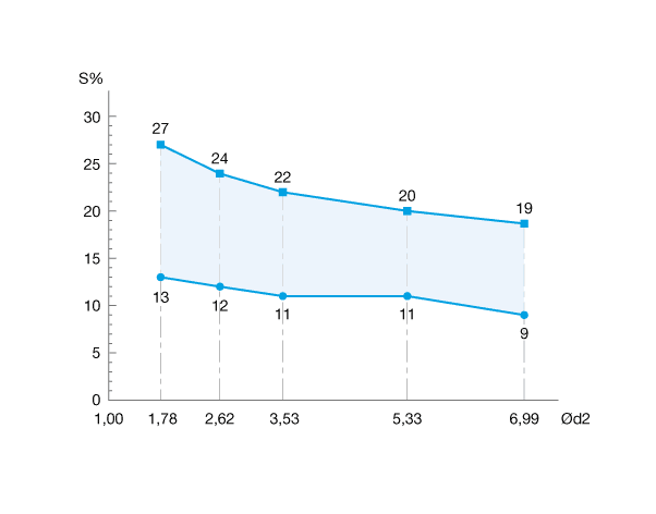
The table below sets out the tightening values (min and max) according to the cross-section Ød2
The table below sets out the design recommendations - Rectangular groove - Dynamic hydraulic sealing for linear movements
| Cross-section Ød2 |
Groove depth t 0/+0,05 |
Groove width L1 0/+0,20 |
Groove radius R1 |
|---|---|---|---|
| 1,50 | 1,10 | 2,25 | 0,30 |
| 1,52 | 1,13 | 2,25 | 0,30 |
| 1,53 | 1,13 | 2,30 | 0,30 |
| 1,60 | 1,20 | 2,40 | 0,30 |
| 1,63 | 1,20 | 2,45 | 0,30 |
| 1,78 | 1,35 | 2,60 | 0,30 |
| 1,80 | 1,35 | 2,60 | 0,30 |
| 1,83 | 1,40 | 2,60 | 0,30 |
| 1,90 | 1,45 | 2,70 | 0,30 |
| 1,98 | 1,50 | 2,80 | 0,30 |
| 2,00 | 1,55 | 2,80 | 0,30 |
| 2,08 | 1,60 | 2,90 | 0,30 |
| 2,10 | 1,60 | 2,90 | 0,30 |
| 2,20 | 1,70 | 3,00 | 0,30 |
| 2,21 | 1,70 | 3,00 | 0,30 |
| 2,30 | 1,80 | 3,10 | 0,30 |
| 2,34 | 1,85 | 3,20 | 0,30 |
| 2,40 | 1,90 | 3,20 | 0,30 |
| 2,46 | 1,95 | 3,30 | 0,30 |
| 2,50 | 1,95 | 3,40 | 0,30 |
| 2,62 | 2,05 | 3,50 | 0,30 |
| 2,65 | 2,10 | 3,50 | 0,30 |
| 2,70 | 2,15 | 3,60 | 0,30 |
| 2,80 | 2,25 | 4,00 | 0,60 |
| 2,92 | 2,35 | 4,20 | 0,60 |
| 2,95 | 2,35 | 4,20 | 0,60 |
| 3,00 | 2,40 | 4,30 | 0,60 |
| 3,10 | 2,50 | 4,40 | 0,60 |
| 3,15 | 2,55 | 4,50 | 0,60 |
| 3,50 | 2,85 | 4,90 | 0,60 |
| 3,53 | 2,85 | 4,90 | 0,60 |
| 3,55 | 2,90 | 4,90 | 0,60 |
| 3,60 | 2,95 | 4,90 | 0,60 |
| 4,00 | 3,25 | 5,40 | 0,60 |
| 4,50 | 3,70 | 5,90 | 0,60 |
| 5,00 | 4,10 | 6,60 | 0,60 |
| 5,30 | 4,40 | 6,80 | 0,60 |
| 5,33 | 4,40 | 6,80 | 0,60 |
| 5,50 | 4,65 | 6,80 | 0,60 |
| 5,70 | 4,80 | 7,10 | 0,60 |
| 6,00 | 5,10 | 7,40 | 0,60 |
| 6,50 | 5,50 | 8,60 | 1,00 |
| 6,99 | 5,90 | 9,20 | 1,00 |
| 7,00 | 5,90 | 9,20 | 1,00 |
| 7,50 | 6,50 | 9,50 | 1,00 |
| 8,00 | 7,00 | 9,90 | 1,00 |
| 8,40 | 7,30 | 10,30 | 1,00 |
| 9,00 | 7,80 | 11,20 | 1,50 |
| 9,50 | 8,10 | 11,90 | 1,50 |
| 10,00 | 8,80 | 12,00 | 2,00 |
| 12,00 | 10,60 | 14,30 | 2,00 |
These values are provided for information purposes only. We recommend refining your design using our O'Ring calculator, which is available free in the "Tools" tab on the website.
O'Rings can be used for rotational movements in certain less aggressive and casual applications. However, other seal profiles are prioritised for such applications (see the rotary seals range). In general, O'Rings have a tendency to contract under the effects of heat, which increases tightening on the rotating shaft, preventing the formation of a lubricating film and increasing friction at the same time. In order to prevent this type of significant wear, we recommend selecting an O'Ring dimension where the outside diameter of the O'Ring is 0.5% to 5% larger than the groove diameter Ød6 in the shaft seal. Conversely, the inside diameter Ød1 of the O'Ring must be 0.5% to 5% smaller than the groove diameter Ød3.
Rubber-based materials with MOS₂ or PTFE reduce friction and increase the lifespan of O'Rings. The table below sets out the installation dimensions to follow.
The table below sets out the tightening values (min and max) according to the cross-section Ød2

The table below sets out the design recommendations - Rectangular groove - Dynamic hydraulic sealing for rotating movements
| Cross-section Ød2 |
Groove depth t 0/+0,05 |
Groove width L1 0/+0,20 |
Groove radius R1 |
|---|---|---|---|
| 1,50 | 1,10 | 2,25 | 0,30 |
| 1,52 | 1,13 | 2,25 | 0,30 |
| 1,53 | 1,13 | 2,30 | 0,30 |
| 1,60 | 1,20 | 2,40 | 0,30 |
| 1,63 | 1,20 | 2,45 | 0,30 |
| 1,78 | 1,35 | 2,60 | 0,30 |
| 1,80 | 1,35 | 2,60 | 0,30 |
| 1,83 | 1,40 | 2,60 | 0,30 |
| 1,90 | 1,45 | 2,70 | 0,30 |
| 1,98 | 1,50 | 2,80 | 0,30 |
| 2,00 | 1,55 | 2,80 | 0,30 |
| 2,08 | 1,60 | 2,90 | 0,30 |
| 2,10 | 1,60 | 2,90 | 0,30 |
| 2,20 | 1,70 | 3,00 | 0,30 |
| 2,21 | 1,70 | 3,00 | 0,30 |
| 2,30 | 1,80 | 3,10 | 0,30 |
| 2,34 | 1,85 | 3,20 | 0,30 |
| 2,40 | 1,90 | 3,20 | 0,30 |
| 2,46 | 1,95 | 3,30 | 0,30 |
| 2,50 | 1,95 | 3,40 | 0,30 |
| 2,62 | 2,05 | 3,50 | 0,30 |
| 2,65 | 2,10 | 3,50 | 0,30 |
| 2,70 | 2,15 | 3,60 | 0,30 |
| 2,80 | 2,25 | 4,00 | 0,60 |
| 2,92 | 2,35 | 4,20 | 0,60 |
| 2,95 | 2,35 | 4,20 | 0,60 |
| 3,00 | 2,40 | 4,30 | 0,60 |
| 3,10 | 2,50 | 4,40 | 0,60 |
| 3,15 | 2,55 | 4,50 | 0,60 |
| 3,50 | 2,85 | 4,90 | 0,60 |
| 3,53 | 2,85 | 4,90 | 0,60 |
| 3,55 | 2,90 | 4,90 | 0,60 |
| 3,60 | 2,95 | 4,90 | 0,60 |
| 4,00 | 3,25 | 5,40 | 0,60 |
| 4,50 | 3,70 | 5,90 | 0,60 |
| 5,00 | 4,10 | 6,60 | 0,60 |
| 5,30 | 4,40 | 6,80 | 0,60 |
| 5,33 | 4,40 | 6,80 | 0,60 |
| 5,50 | 4,65 | 6,80 | 0,60 |
| 5,70 | 4,80 | 7,10 | 0,60 |
| 6,00 | 5,10 | 7,40 | 0,60 |
| 6,50 | 5,50 | 8,60 | 1,00 |
| 6,99 | 5,90 | 9,20 | 1,00 |
| 7,00 | 5,90 | 9,20 | 1,00 |
| 7,50 | 6,50 | 9,50 | 1,00 |
| 8,00 | 7,00 | 9,90 | 1,00 |
| 8,40 | 7,30 | 10,30 | 1,00 |
| 9,00 | 7,80 | 11,20 | 1,50 |
| 9,50 | 8,10 | 11,90 | 1,50 |
| 10,00 | 8,80 | 12,00 | 2,00 |
| 12,00 | 10,60 | 14,30 | 2,00 |
These values are provided for information purposes only. We recommend refining your design using our O'Ring calculator, which is available free in the "Tools" tab on the website.
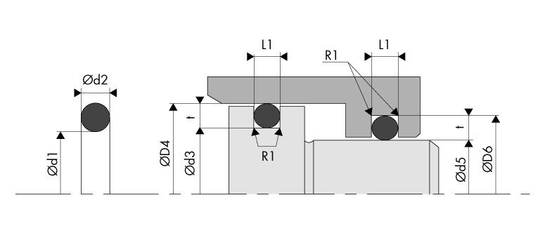
The float-mounting principle, without radial deformation on the O'Ring, is mainly used for pneumatic applications. When pressurised, a volume of air leaks out until the gap is filled between the piston and the cylinder (piston seal) or between the rod and the tip of the cylinder (rod seal).
For rod sealing (inside sealing), the dimension of the O'Ring should be selected so that the inside diameter Ød1 of the O'Ring is 0.5% to 5% smaller than the rod diameter Ød5.
For piston sealing (outside sealing), the dimension of the O'Ring should be selected so that the outside diameter of the O'Ring is 0.5% to 5% larger than the groove diameter Ød3.
The table below sets out the design recommendations - Rectangular groove - Pneumatic sealing - Float-mounted fitting
| Cross-section Ød2 |
Groove depth t 0/+0,05 |
Groove width L1 0/+0,20 |
Groove radius R1 |
|---|---|---|---|
| 1,50 | 1,75 | 1,65 | 0,30 |
| 1,52 | 1,80 | 1,65 | 0,30 |
| 1,53 | 1,80 | 1,70 | 0,30 |
| 1,60 | 1,85 | 1,75 | 0,30 |
| 1,63 | 1,85 | 1,75 | 0,30 |
| 1,78 | 2,05 | 1,95 | 0,30 |
| 1,80 | 2,05 | 1,95 | 0,30 |
| 1,83 | 2,10 | 2,00 | 0,30 |
| 1,90 | 2,20 | 2,05 | 0,30 |
| 1,98 | 2,30 | 2,20 | 0,30 |
| 2,00 | 2,30 | 2,20 | 0,30 |
| 2,08 | 2,35 | 2,30 | 0,30 |
| 2,10 | 2,40 | 2,30 | 0,30 |
| 2,20 | 2,50 | 2,40 | 0,30 |
| 2,21 | 2,50 | 2,40 | 0,30 |
| 2,30 | 2,60 | 2,50 | 0,30 |
| 2,34 | 2,65 | 2,50 | 0,30 |
| 2,40 | 2,70 | 2,60 | 0,30 |
| 2,46 | 2,85 | 2,65 | 0,30 |
| 2,50 | 2,80 | 2,70 | 0,30 |
| 2,62 | 2,95 | 2,95 | 0,30 |
| 2,65 | 2,95 | 2,95 | 0,30 |
| 2,70 | 3,10 | 2,90 | 0,30 |
| 2,80 | 3,20 | 3,00 | 0,60 |
| 2,92 | 3,30 | 3,15 | 0,60 |
| 2,95 | 3,40 | 3,20 | 0,60 |
| 3,00 | 3,45 | 3,30 | 0,60 |
| 3,10 | 3,50 | 3,40 | 0,60 |
| 3,15 | 3,60 | 3,40 | 0,60 |
| 3,50 | 4,00 | 3,80 | 0,60 |
| 3,53 | 4,00 | 3,80 | 0,60 |
| 3,55 | 4,05 | 3,80 | 0,60 |
| 3,60 | 4,05 | 3,80 | 0,60 |
| 4,00 | 4,55 | 4,30 | 0,60 |
| 4,50 | 4,95 | 4,80 | 0,60 |
| 5,00 | 5,45 | 5,30 | 0,60 |
| 5,30 | 5,75 | 5,50 | 0,60 |
| 5,33 | 5,80 | 5,60 | 0,60 |
| 5,50 | 6,00 | 5,80 | 0,60 |
| 5,70 | 6,20 | 6,00 | 0,60 |
| 6,00 | 6,50 | 6,30 | 0,60 |
| 6,50 | 7,00 | 6,80 | 1,00 |
| 6,99 | 7,50 | 7,30 | 1,00 |
| 7,00 | 7,50 | 7,30 | 1,00 |
| 7,50 | 8,10 | 7,80 | 1,00 |
| 8,00 | 8,50 | 8,30 | 1,00 |
| 8,40 | 9,00 | 8,70 | 1,00 |
| 9,00 | 9,60 | 9,30 | 1,50 |
| 9,50 | 10,10 | 9,85 | 1,50 |
| 10,00 | 10,60 | 10,35 | 2,00 |
| 12,00 | 12,70 | 12,40 | 2,00 |
These values are provided for information purposes only. We recommend refining your design using our O'Ring calculator, which is available free in the "Tools" tab on the website.
With often problematic lubrication conditions, correct O'Ring operation in linear motion can be achieved with a very reduced radial deformation.
For rod sealing (inside sealing), the dimension of the O'Ring should be selected so that the outside diameter of the O'Ring is 0.5% to 5% greater than the groove diameter Ød6.
For piston sealing (outside sealing), the dimension of the O'Ring should be selected so that the inside diameter Ød1 of the O'Ring is 0.5% to 5% smaller than the groove diameter Ød3.
The table below sets out the tightening values (min and max) according to the cross-section Ød2
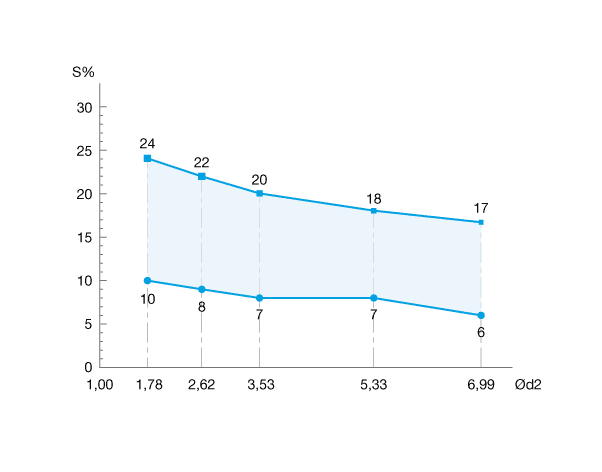
The table below sets out the design recommendations - Rectangular groove - Pneumatic sealing - Non-float-mounted fitting
| Cross-section Ød2 |
Groove depth t 0/+0,05 |
Groove width L1 0/+0,20 |
Groove radius R1 |
|---|---|---|---|
| 0,50 | 0,30 | 1,20 | 0,20 |
| 0,74 | 0,53 | 1,30 | 0,20 |
| 1,00 | 1,60 | 1,55 | 0,20 |
| 1,02 | 0,75 | 1,60 | 0,20 |
| 1,20 | 0,90 | 1,80 | 0,20 |
| 1,25 | 0,93 | 1,85 | 0,20 |
| 1,27 | 0,95 | 1,85 | 0,20 |
| 1,30 | 0,98 | 1,90 | 0,20 |
| 1,42 | 1,08 | 2,10 | 0,30 |
| 1,50 | 1,15 | 2,20 | 0,30 |
| 1,52 | 1,18 | 2,20 | 0,30 |
| 1,53 | 1,18 | 2,20 | 0,30 |
| 1,60 | 1,23 | 2,30 | 0,30 |
| 1,63 | 1,25 | 2,40 | 0,30 |
| 1,78 | 1,40 | 2,50 | 0,30 |
| 1,80 | 1,43 | 2,50 | 0,30 |
| 1,83 | 1,45 | 2,50 | 0,30 |
| 1,90 | 1,53 | 2,60 | 0,30 |
| 1,98 | 1,60 | 2,70 | 0,30 |
| 2,00 | 1,60 | 2,70 | 0,30 |
| 2,08 | 1,70 | 2,70 | 0,30 |
| 2,10 | 1,70 | 2,70 | 0,30 |
| 2,20 | 1,80 | 2,80 | 0,30 |
| 2,21 | 1,80 | 2,80 | 0,30 |
| 2,30 | 1,85 | 3,00 | 0,30 |
| 2,34 | 1,90 | 3,00 | 0,30 |
| 2,40 | 1,95 | 3,10 | 0,30 |
| 2,46 | 2,00 | 3,20 | 0,30 |
| 2,50 | 2,05 | 3,20 | 0,30 |
| 2,62 | 2,15 | 3,30 | 0,30 |
| 2,65 | 2,20 | 3,30 | 0,30 |
| 2,70 | 2,25 | 3,50 | 0,30 |
| 2,80 | 2,35 | 3,90 | 0,60 |
| 2,92 | 2,45 | 4,00 | 0,60 |
| 2,95 | 2,50 | 4,00 | 0,60 |
| 3,00 | 2,55 | 4,10 | 0,60 |
| 3,10 | 2,60 | 4,20 | 0,60 |
| 3,15 | 2,65 | 4,20 | 0,60 |
| 3,50 | 2,95 | 4,60 | 0,60 |
| 3,53 | 3,00 | 4,60 | 0,60 |
| 3,55 | 3,00 | 4,60 | 0,60 |
| 3,60 | 3,05 | 4,70 | 0,60 |
| 4,00 | 3,45 | 5,10 | 0,60 |
| 4,50 | 3,85 | 5,60 | 0,60 |
| 5,00 | 4,30 | 6,30 | 0,60 |
| 5,30 | 4,55 | 6,50 | 0,60 |
| 5,33 | 4,55 | 6,50 | 0,60 |
| 5,50 | 4,80 | 6,60 | 0,60 |
| 5,70 | 5,00 | 6,80 | 0,60 |
| 6,00 | 5,25 | 7,10 | 0,60 |
| 6,50 | 5,65 | 8,20 | 1,00 |
| 6,99 | 6,10 | 8,80 | 1,00 |
| 7,00 | 6,10 | 8,80 | 1,00 |
| 7,50 | 6,65 | 9,10 | 1,00 |
| 8,00 | 7,10 | 9,60 | 1,00 |
| 8,40 | 7,40 | 10,10 | 1,00 |
| 9,00 | 7,90 | 11,90 | 1,50 |
| 9,50 | 8,40 | 12,30 | 1,50 |
| 10,00 | 8,90 | 14,30 | 2,00 |
| 12,00 | 10,70 | 16,30 | 2,00 |
These values are provided for information purposes only. We recommend refining your design using our O'Ring calculator, which is available free in the "Tools" tab on the website.
Against the extrusion of O'Rings under significant pressures, it's best to use back-up rings, BECA 008, BECA 008 P, BECA 011 and BECA 012, and O'Rings with a hardness of 70 Shore A, in line with the following parameters:
- - Pressures above 5.0 MPa for diameters Ød1 > 50,00 mm
- - Pressures above 10.0 MPa for diameters Ød1 ≤ 50,00 mm
However, this is not always possible if there is a lack of space in the housing. In this case, the tolerances of the mechanical parts must be adapted depending on the cross-section and the O'Ring hardness. It is important to scrupulously observe the extrusion gaps to prevent any O'Ring creep, which would lead to its complete destruction.

| Cross-section Ød2 | < 2,00 | 2,00 - 3,00 | 3,00 - 5,00 | 5,00 - 7,00 | > 7,00 |
|---|---|---|---|---|---|
| Hardness of 70 Shore A | |||||
| Pressure | Radial extrusion gap | ||||
| ≤ 3,50 | 0,08 | 0,09 | 0,10 | 0,13 | 0,15 |
| ≤ 7,00 | 0,05 | 0,07 | 0,09 | 0,09 | 0,10 |
| ≤ 10,50 | 0,03 | 0,04 | 0,07 | 0,07 | 0,08 |
| Hardness of 80 Shore A | |||||
| Pressure | Radial extrusion gap | ||||
| ≤ 3,50 | 0,10 | 0,13 | 0,15 | 0,18 | 0,20 |
| ≤ 7,00 | 0,07 | 0,09 | 0,10 | 0,13 | 0,15 |
| ≤ 10,50 | 0,05 | 0,07 | 0,08 | 0,09 | 0,10 |
| ≤ 14,00 | 0,03 | 0,04 | 0,05 | 0,07 | 0,08 |
| ≤ 17,50 | 0,02 | 0,03 | 0,03 | 0,04 | 0,04 |
| Hardness of 90 Shore A | |||||
| Pressure | Radial extrusion gap | ||||
| ≤ 3,50 | 0,13 | 0,15 | 0,18 | 0,20 | 0,23 |
| ≤ 7,00 | 0,10 | 0,13 | 0,15 | 0,18 | 0,20 |
| ≤ 10,50 | 0,07 | 0,09 | 0,10 | 0,13 | 0,15 |
| ≤ 14,00 | 0,05 | 0,07 | 0,08 | 0,09 | 0,10 |
| ≤ 17,50 | 0,04 | 0,05 | 0,07 | 0,08 | 0,09 |
| ≤ 21,00 | 0,03 | 0,04 | 0,05 | 0,07 | 0,08 |
| ≤ 35,00 | 0,02 | 0,03 | 0,03 | 0,04 | 0,04 |
To make the tubes and rods, we recommend using non-porous steel or cast iron. For dynamic applications, brass and untreated stainless steel, as well as aluminium, are not as hard and are therefore not recommended, as they would be subjected to a lot of wear.
The roughness means that the sealing must be of a high quality. The surface roughness of grooves improves during alternating pressures.
| Type of application | Type of surface | Roughness Ra |
Roughness Rz |
Roughness Rmax |
|---|---|---|---|---|
| Radial - Static | Under non-pulsating pressure | |||
| Mating surface (rod and cylinder) | 1,6 µm | 6,3 µm | 10,0 µm | |
| Groove diameter and groove flanks | 1,6 µm | 6,3 µm | 10,0 µm | |
| Under pulsating pressure | ||||
| Mating surface (rod and cylinder) | 0,8 µm | 3,2 µm | 5,0 µm | |
| Groove diameter and groove flanks | 1,6 µm | 6,3 µm | 10,0 µm | |
| Radial - Dynamic | Mating surface (rod and cylinder) | 0,4 µm | 1,6 µm | 2,5 µm |
| Groove diameter and groove flanks | 0,8 µm | 3,2 µm | 5,0 µm | |
| Axial - Static | Clamping surface | 1,6 µm | 6,3 µm | 10,0 µm |
| Groove flanks | 1,6 µm | 6,3 µm | 10,0 µm | |
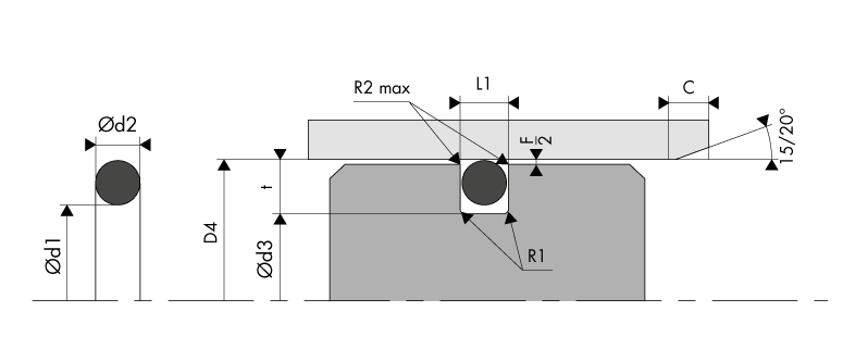
Given that the O'Rings are fitted pre-tightened, the chamfer lengths and rounded cutting edges must fit with the table below.
| Cross-section Ød2 |
Radius R1 |
Max radius R2 |
Chamfer C |
|
|---|---|---|---|---|
| 15° | 20° | |||
| 1,78 - 1,80 | 0,30 | 0,20 | 2,50 | 2,00 |
| 2,62 - 2,65 | 0,30 | 0,20 | 3,00 | 2,50 |
| 3,53 - 3,55 | 0,60 | 0,20 | 3,50 | 3,00 |
| 5,33 - 5,30 | 0,60 | 0,20 | 4,00 | 3,50 |
| 6,99 - 7,00 | 1,00 | 0,20 | 5,00 | 4,00 |
| 8,40 | 1,00 | 0,20 | 6,00 | 4,50 |
Quality criteria
The table below sets out the maximum limits for O'Ring appearance defects, in line with standard ISO 3601-3.
| Type of surface defect | Schematic presentation | Dimension limits | Maximum limits for defects on the cross-section Ød2 | ||||||
|---|---|---|---|---|---|---|---|---|---|
| > 0,80 ≤ 2,25 | > 2,25 ≤ 3,15 | > 3,15 ≤ 4,50 | > 4,50 ≤ 6,30 | > 6,30 ≤ 8,40 | |||||
| Offset | 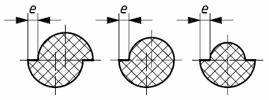 |
e | 0,08 | 0,10 | 0,13 | 0,15 | 0,15 | ||
| Flash | 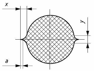 |
x | 0,10 | 0,12 | 0,4 | 0,16 | 0,18 | ||
| y | 0,10 | 0,12 | 0,4 | 0,16 | 0,18 | ||||
| a | When the flash can be differentiated, it must not be greater than 0,07 mm. | ||||||||
| Backrind | 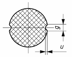 |
g | 0,18 | 0,27 | 0,36 | 0,53 | 0,70 | ||
| u | 0,08 | 0,08 | 0,10 | 0,10 | 0,13 | ||||
| Area of excessive trimming (radial tool marks not allowed) | 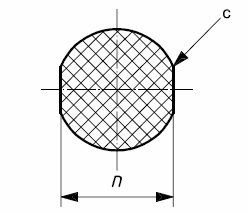 |
n | Trimming is allowed if the dimensionn is not less than the minimum diameter d2 of the O'Ring | ||||||
| Filling mark (folds must not be radial) | 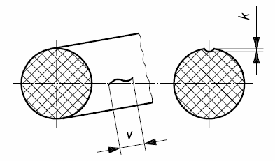 |
v | 1,50 a | 1,50 a | 6,50 a | 6,50 a | 6,50 a | ||
| k | 0,08 | 0,08 | 0,08 | 0,08 | 0,08 | ||||
| Lack of material and tearing (including O'Ring tearing) | 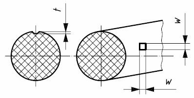 |
w | 0,60 | 0,80 | 1,00 | 1,30 | 1,70 | ||
| t | 0,08 | 0,08 | 0,10 | 0,10 | 0,13 | ||||
| a: or 0.05 times the inside diameter of the O'Ring d1, taking the largest of the two values. | |||||||||
Assembly recommendations
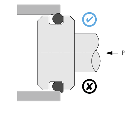
Several essential rules must be followed before fitting the O'Rings:
- Check that the mechanical parts (rod and bore parts) have a chamfer length that is in line with our recommendations,
- Remove the flash and chamfer or round off the sharp edges and holes; cover the threaded parts,
- Remove the machining shavings and all impurities and other foreign bodies. Thoroughly clean all of the mechanical parts,
- Grease or oil the O'Ring and mechanical parts to make it easier to fit. For this purpose, ensure upstream that the lubricants are compatible with the O'Ring materials. Avoid greases containing solid additives (molybdenum disulfide or zinc sulfide),
- If using installation tools, check that they are clean and do not have sharp edges.
Piston installation with O'Rings
Rod installation with O'Rings
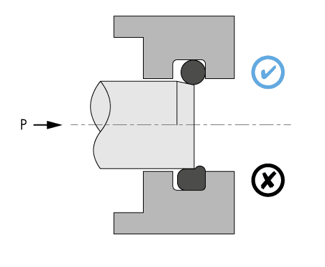
O'Rings installation with transverse holes
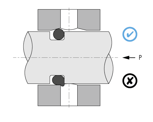
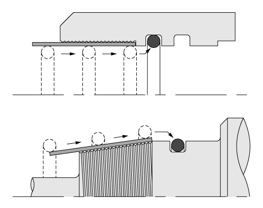
O'Rings installation with threaded parts
